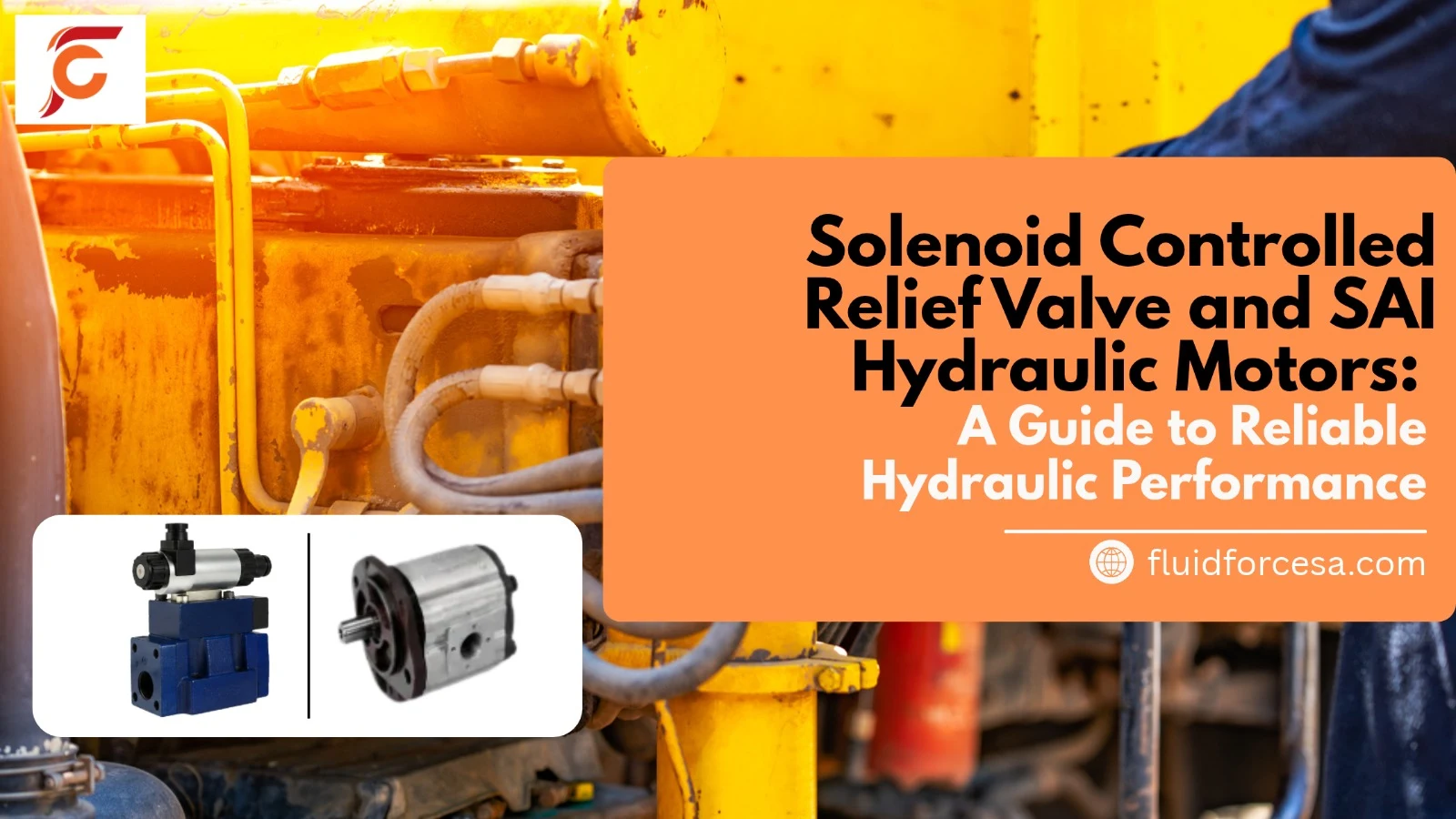
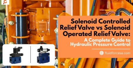
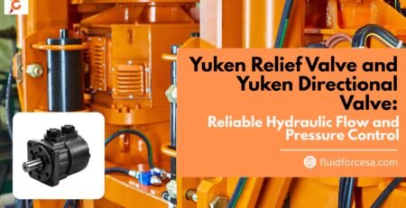
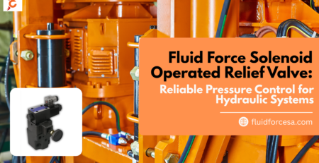
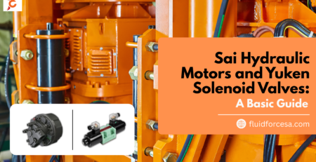
A solenoid controlled relief valve regulates hydraulic pressure through electrically operated control, helping protect hydraulic systems from excessive pressure and supporting automated machine operation. SAI hydraulic motors convert hydraulic energy into mechanical rotation, delivering controlled torque and reliable performance in demanding industrial applications. When selected according to system pressure, flow rate, torque requirements, and operating conditions, these components contribute to efficient and dependable hydraulic performance.
Introduction
Hydraulic systems play an essential role in modern industries, including manufacturing, construction, agriculture, material handling, and heavy machinery. Their ability to transmit substantial force through pressurized fluid makes them suitable for applications that require precision, power, and consistent operation.
Two important components in these systems are solenoid controlled relief valves and hydraulic motors. Relief valves help manage pressure, while hydraulic motors provide the rotational force needed to operate machinery. Understanding their functions, benefits, and selection criteria can help businesses build safer and more efficient hydraulic systems.
What Is a Solenoid Controlled Relief Valve?
A solenoid controlled relief valve is a hydraulic pressure-control component that uses an electrical solenoid to operate or control a valve mechanism. Depending on its design, it can provide electrically controlled pressure relief, switching between operating conditions, or remote pressure control.
When hydraulic pressure reaches the valve’s configured relief setting, the valve allows fluid to flow through a relief path, limiting pressure and helping protect system components. In solenoid-operated designs, electrical signals determine when or how the valve operates.
How Does It Work?
The working principle generally involves the following steps:
- Electrical signal: A control system energizes or de-energizes the solenoid according to the required operating condition.
- Valve actuation: The solenoid moves a plunger or operates a pilot mechanism, depending on the valve design.
- Pressure regulation: The valve responds to hydraulic pressure and its configured control settings.
- Fluid diversion: When the relief condition is reached, hydraulic fluid is directed toward the tank or another designated return path.
- System protection: Limiting excessive pressure helps reduce the risk of damage to pumps, hoses, seals, and other hydraulic components.
The exact sequence depends on whether the valve uses direct-acting, pilot-operated, or electrically switched pressure-control technology. Correct installation and configuration are essential for safe operation.
Key Benefits of Solenoid Controlled Relief Valves
- Pressure protection: Helps prevent hydraulic pressure from exceeding the intended operating limit.
- Electrical control: Supports integration with programmable logic controllers (PLCs), automation systems, and electrical control panels.
- Remote operation: Allows pressure-control functions to be managed from a central control system when supported by the design.
- Improved operating flexibility: Enables different pressure settings or operating modes in suitable hydraulic circuits.
- Equipment protection: Helps reduce the risk of pressure-related damage and unexpected downtime.
- Industrial versatility: Suitable for various hydraulic applications when its pressure, flow, and electrical specifications match system requirements.
Common Applications
Solenoid controlled relief valves are used in hydraulic power units, industrial presses, injection moulding equipment, machine tools, construction machinery, and automated production lines.
They are particularly useful when hydraulic pressure must be controlled as part of a coordinated electrical and hydraulic operating sequence.
What Are SAI Hydraulic Motors?
SAI hydraulic motors are hydraulic rotary actuators associated with the SAI brand, which offers hydraulic motor technologies for industrial and mobile machinery applications. These motors convert hydraulic fluid energy into rotational mechanical energy, allowing equipment to drive rotating mechanisms under load.
Depending on the model and motor design, they may be selected for applications requiring high torque, controlled rotation, or operation under demanding load conditions.
Businesses evaluating SAI hydraulic motors should review the manufacturer’s specifications for the exact model rather than assuming that every motor has the same operating characteristics.
How Do Hydraulic Motors Work?
Hydraulic motors operate by converting the energy of pressurized hydraulic fluid into shaft rotation.
The process typically follows these stages:
- A hydraulic pump supplies pressurized fluid to the motor.
- Fluid enters the motor through its designated inlet port.
- Internal hydraulic forces act on the motor’s rotating mechanism.
- The mechanism produces torque and turns the output shaft.
- Fluid exits through the return port and flows back into the hydraulic circuit.
The motor’s speed is primarily influenced by the supplied flow rate, while its torque depends largely on the pressure differential and motor displacement. Actual performance also depends on mechanical and volumetric efficiency, fluid properties, and operating conditions.
Benefits of SAI Hydraulic Motors
1. High torque capability
Hydraulic motors can deliver substantial rotational force, making them useful for equipment that must move or rotate heavy loads.
2. Controlled operation
When paired with suitable flow-control and pressure-control components, hydraulic motors can support controlled movement and speed regulation.
3. Industrial suitability
Appropriately specified motors can operate in demanding environments, including industrial machinery and mobile hydraulic equipment.
4. Integration flexibility
Hydraulic motors can be incorporated into systems involving pumps, directional control valves, relief valves, filters, and hydraulic power units.
5. Application-specific selection
Different motor configurations allow engineers to match performance characteristics to particular speed, torque, and installation requirements.
Common Applications of SAI Hydraulic Motors
Depending on the model and manufacturer’s approved application range, hydraulic motors may be considered for:
- Industrial machinery and production equipment.
- Material-handling systems.
- Heavy-duty rotating mechanisms.
- Construction and mobile equipment.
- Agricultural machinery.
- Specialized hydraulic drive systems.
Always verify the selected motor’s technical documentation and suitability for the intended application.
Solenoid Controlled Relief Valve and SAI Hydraulic Motors: How They Work Together
A hydraulic motor and a pressure-relief valve can perform complementary functions within the same hydraulic circuit.
The hydraulic motor converts fluid power into rotation, while the relief valve helps protect the circuit against excessive pressure. A solenoid-controlled design can add electrical control capabilities, depending on the valve configuration.
For example, a hydraulic system powering a rotating industrial mechanism may use a hydraulic pump to supply fluid to the motor. A correctly configured relief valve can limit pressure when the system reaches its relief condition. Electrical controls can coordinate the valve’s operation with the machine’s operating sequence when the circuit is designed for that purpose.
However, a relief valve does not independently guarantee accurate motor speed or torque. These characteristics depend on the complete hydraulic circuit, including the pump, flow-control arrangements, motor specifications, and load.
Important Design Considerations
When integrating these components, engineers should evaluate:
- Pressure rating: Confirm that all components are suitable for the system’s maximum operating pressure.
- Flow capacity: Ensure that the valve and motor can accommodate the required hydraulic flow.
- Motor displacement: Select a motor that meets the required speed and torque characteristics.
- Electrical compatibility: Verify the solenoid voltage, current requirements, and control signals.
- Fluid compatibility: Use hydraulic fluid that meets the manufacturer’s viscosity and cleanliness requirements.
- Heat management: Consider pressure losses, fluid temperature, cooling capacity, and operating duty cycle.
- Circuit safety: Provide appropriate pressure protection and account for load-induced pressure, return-line restrictions, and other application-specific hazards.
Step-by-Step Guide to Selecting the Right Hydraulic Components
Choosing the right valve and motor requires a clear understanding of the equipment’s operating requirements.
Step 1: Define the Application
Identify what the hydraulic system must accomplish. Determine whether the application requires continuous rotation, intermittent movement, heavy-load operation, or electrically coordinated pressure control.
Step 2: Calculate the Required Torque and Speed
Estimate the motor’s required output torque and rotational speed. Use the equipment load, transmission arrangement, and duty cycle to establish realistic performance requirements.
Step 3: Determine Operating Pressure and Flow
Calculate the hydraulic pressure and flow needed to achieve the target motor performance. Account for efficiency losses and operating variations.
Step 4: Select the Appropriate Relief Valve
Choose a solenoid controlled relief valve with suitable pressure and flow ratings, solenoid specifications, response characteristics, and control functionality.
Confirm whether the application requires direct-acting or pilot-operated technology and whether the valve provides the intended electrically controlled operating modes.
Step 5: Verify Motor Compatibility
Review the manufacturer’s data for the selected SAI hydraulic motor, including displacement, allowable pressure, speed limits, torque characteristics, shaft configuration, and mounting requirements.
Step 6: Check System Integration
Ensure the valve, motor, pump, hoses, fittings, filters, and reservoir are compatible with one another. Confirm that the circuit provides suitable return-flow capacity and thermal management.
Step 7: Test and Maintain the System
Have qualified personnel commission the hydraulic circuit according to the manufacturer’s instructions. Inspect for leaks, abnormal noise, overheating, pressure instability, and unexpected movement.
Routine maintenance should include checking fluid condition, replacing filters as specified, and inspecting electrical connections and hydraulic components.
Common Mistakes to Avoid
Selecting hydraulic components solely by brand or price can lead to poor performance and unnecessary maintenance costs.
Avoid these common mistakes:
- Choosing a motor without calculating the required torque and speed.
- Selecting a relief valve with insufficient flow capacity.
- Assuming every solenoid-controlled valve provides the same control functions.
- Ignoring fluid cleanliness and viscosity requirements.
- Overlooking electrical compatibility.
- Setting relief pressure without considering component ratings and circuit design.
- Neglecting commissioning, routine inspection, and preventive maintenance.
Correct component selection should always be based on engineering requirements and verified manufacturer documentation.
Frequently Asked Questions (FAQs)
1. What is the main purpose of a solenoid controlled relief valve?
Its primary purpose is to provide pressure-relief functionality with electrical actuation or control. It helps limit excessive hydraulic pressure and can support automated operation, depending on its design.
2. What are SAI hydraulic motors used for?
SAI hydraulic motors convert pressurized hydraulic fluid into rotary mechanical power. Their applications depend on the motor model and may include industrial machinery, mobile equipment, and specialized hydraulic drive systems.
3. Can a solenoid controlled relief valve control hydraulic motor speed?
Not by itself in every circuit. Motor speed is primarily related to hydraulic flow and motor displacement. A suitable flow-control or variable-displacement arrangement is generally required for effective speed control.
4. How do I select the correct hydraulic relief valve?
Consider the maximum system pressure, required flow rate, valve type, electrical specifications, fluid compatibility, and operating conditions. Verify the selection against the manufacturer’s technical documentation.
5. What determines the torque of a hydraulic motor?
Motor torque is largely determined by the pressure differential across the motor and its displacement. Mechanical efficiency and operating conditions also affect the actual output torque.
6. Why is hydraulic fluid maintenance important?
Contaminated or unsuitable fluid can increase wear, affect valve operation, damage internal motor components, and reduce system reliability. Following the manufacturer’s fluid and filtration recommendations helps maintain performance.
7. Where can businesses find hydraulic components and technical support?
Businesses should consult established hydraulic equipment suppliers that provide clear product specifications, compatibility information, and appropriate technical assistance. For component sourcing, compare available specifications with the actual requirements of the hydraulic system.
Conclusion
Solenoid controlled relief valves and SAI hydraulic motors serve different but complementary purposes in hydraulic engineering. Relief valves help manage excessive pressure, while hydraulic motors convert hydraulic energy into rotational power for industrial and mobile applications.
Reliable performance depends on selecting components according to pressure, flow, torque, speed, electrical compatibility, and operating conditions. Proper circuit design, professional commissioning, and preventive maintenance further support equipment safety and service life.
Author Bio
Author: Industrial Engineering Content Team
The Industrial Engineering Content Team develops educational resources on hydraulic systems, industrial equipment, automation, and component selection. Its content focuses on explaining engineering principles, practical selection criteria, and maintenance considerations to help readers make informed decisions. Technical specifications should always be verified against the relevant manufacturer’s documentation.