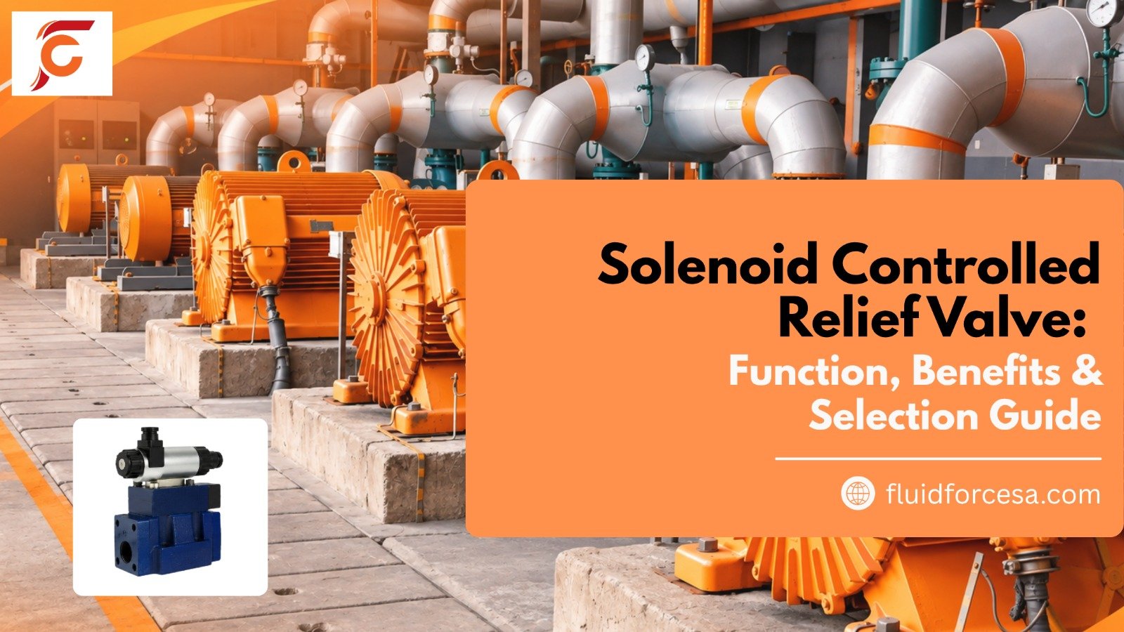
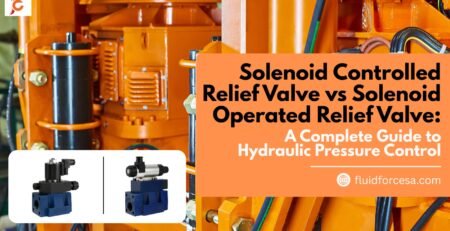
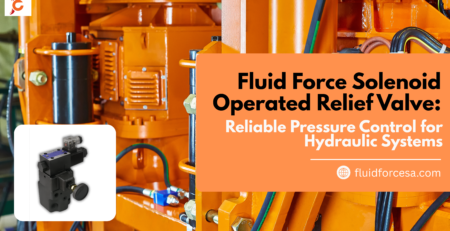
In today’s industrial hydraulic systems, pressure control is no longer just about protection, it’s about efficiency, flexibility and remote operation. A solenoid controlled relief valve (also known as a solenoid operated relief valve) delivers exactly that combination by integrating a pilot-operated relief valve with a solenoid directional valve in one compact unit.
Understanding the Core Function
These valves limit maximum system pressure by directing excess flow to tank once the set point is reached. What makes them different from a standard relief valve is the built-in solenoid. By energising or de-energising the solenoid, operators can:
- Unload the pump at low pressure during idle periods
- Restore the original relief setting instantly
- Switch between two or three different pressure levels
All of this happens without additional external piping, reducing potential leak points and simplifying manifold design.
Key Benefits for Industrial Applications
- Energy savings through remote pump unloading
- Cleaner, more compact system layouts
- Faster response for motor start/stop and actuator deceleration
- Easy integration with PLCs and automated controls
- Reliable over-pressure protection for pumps, cylinders and motors
These advantages make the valve especially useful in hydraulic power units, presses, machine tools and material-handling equipment.
How the Valve Operates
The design is two-stage. System pressure is sensed at the inlet. A small pilot flow controls the main stage (usually a balanced piston or poppet). When pressure reaches the spring setting, the pilot opens and the main stage lifts, dumping flow to tank.
The solenoid sits on the vent port. Venting the pilot chamber causes the main stage to open at very low pressure (unload mode). Blocking the vent restores the set relief pressure. Different spool options allow normally vented, normally relieving, or multi-pressure configurations.
Tank-line back pressure adds directly to the relief setting, so good tank-line design remains important. Some models include a vent restrictor to soften transitions and reduce shock.
Common Options Available
- Single-solenoid or double-solenoid versions
- Sub-plate or threaded mounting
- Flow capacities typically from 100 L/min upward
- Pressure ratings commonly 210–350 bar
- AC or DC coils with various connectors
- Optional vent-restrictor or high-venting designs
- Cartridge versions for compact manifolds
Selection Checklist
- Confirm maximum system pressure and required relief setting.
- Calculate peak flow that must be relieved.
- Decide whether you need simple unload/load, dual pressure or multi-pressure control.
- Match electrical requirements (voltage, connector, duty cycle).
- Choose the correct mounting style for your manifold or power unit.
- Account for possible tank-line back pressure.
- Install with clean fluid and proper filtration, then set and verify at operating temperature.
Practical Tips for Best Results
- Pair a normally vented version with fixed-displacement pumps so the system unloads automatically when not working.
- Use the valve in hi-lo pump circuits to unload the high-volume pump once the low-pressure threshold is reached.
- Keep tank lines short and adequately sized to avoid unwanted pressure rise.
Frequently Asked Questions
How does it differ from a standard relief valve?
A standard relief valve is purely mechanical. A solenoid controlled version adds remote electrical unloading or multi-pressure selection without extra piping.
Can it unload a fixed-displacement pump?
Yes — this is one of its most common and valuable uses.
Do these valves require special cleanliness levels?
They perform best with clean fluid. Maintain proper filtration to protect the pilot orifice and solenoid spool.
How quickly do they respond?
Typically within tens of milliseconds
.
Conclusion
Choosing the right solenoid controlled relief valve (or solenoid operated relief valve) gives hydraulic systems both dependable over-pressure protection and practical electrical control. The integrated design removes extra piping, improves reliability and supports more energy-efficient fixed-pump circuits.
Match flow capacity, pressure range, solenoid configuration, and mounting style to the actual duty cycle for safer operation, lower energy consumption, and longer component life.
Author Bio
Fluid Force Technical Team
Fluid Force supplies industrial hydraulic components including manifold blocks, power units and branded valves and accessories. The team supports customers with practical selection guidance and reliable solutions for hydraulic system design and maintenance.